Objective: Configure lab devices with management IP addresses, enable SSH, and establish basic routing so that the Ubuntu workstation (Ubuntu‑WS) can reach every device. This foundational lab ensures that all subsequent automation tasks have a reliable and secure management network.
Why are we doing this? Before we can write Python scripts, use Ansible, or call APIs, we need a fully reachable and consistently configured environment. By the end of this lab, you will have a stable topology where Ubuntu‑WS can ping and SSH to every network device.
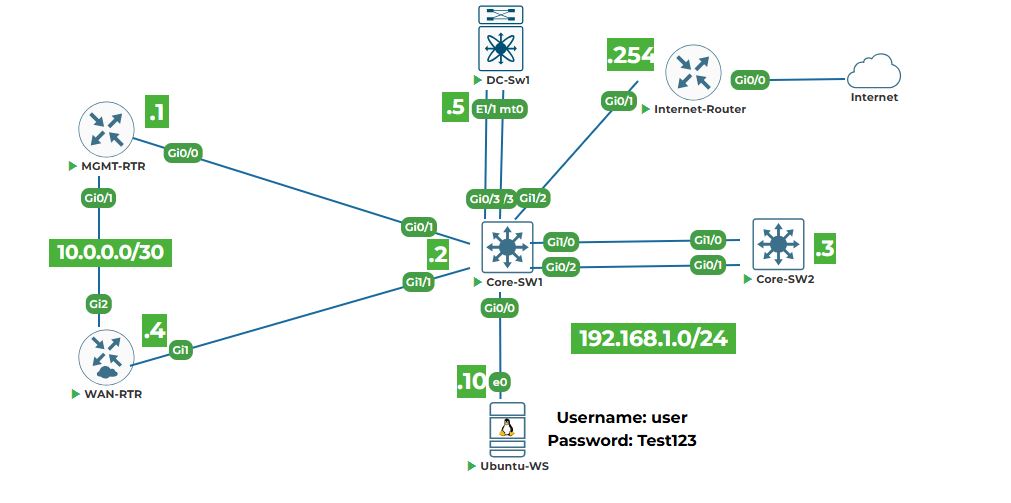
Task 1: Access the Device Consoles
Step 1: Open your lab topology.
2. Right-click on each device and select start. Once devices are powered on then click on each device icons, the “Console” will open in the new tab. You will need to configure each device one by one. Keep all console windows open.
Note: All devices are in a factory default state and have trial licenses. No initial configuration exists.
Task 2: Configure MGMT‑RTR (Cisco IOSv Router)
Step 1: In the MGMT‑RTR console, enter global configuration mode and set the hostname.
enable
configure terminal
hostname MGMT-RTR
Step 2: Configure interface GigabitEthernet0/0 with the management IP address and enable the interface.
interface GigabitEthernet0/0
ip address 192.168.1.1 255.255.255.0
no shutdown
exit
Step 3: Enable SSH and generate RSA keys (required for secure access).
ip domain-name lab.local
crypto key generate rsa modulus 2048
ip ssh version 2
line vty 0 4
transport input ssh
login local
exit
Step 4: Create a local user for SSH authentication.
username admin privilege 15 secret uninets@123
Step 5: Optionally, set a default route (though not strictly needed for management subnet).
ip route 0.0.0.0 0.0.0.0 192.168.1.254 (if an upstream router exists; otherwise skip)
Explanation: The management network is directly connected, so a default route is optional. We add it for completeness.
Step 6: Exit configuration mode and verify the IP address.
end
show ip interface brief
You should see GigabitEthernet0/0 with IP 192.168.1.1 and status “up/up”.
Task 3: Configure CORE‑SW1 (Cisco IOSvL2 Switch)
Step 1: In the CORE‑SW1 console, set the hostname.
enable
configure terminal
hostname CORE-SW1
Step 2: Configure the management VLAN interface (VLAN 1) with an IP address.
interface vlan 1
ip address 192.168.1.2 255.255.255.0
no shutdown
exit
Step 3: Set the default gateway to point to MGMT‑RTR.
ip default-gateway 192.168.1.1
Step 4: Enable SSH and create a local user.
ip domain-name lab.local
crypto key generate rsa modulus 2048
ip ssh version 2
username admin privilege 15 secret uninets@123
line vty 0 4
transport input ssh
login local
exit
Step 5: Save the configuration.
end
write memory
Note: On IOSvL2, the command is write memory or copy running-config startup-config.
Task 4: Configure CORE‑SW2 (Cisco IOSvL2 Switch)
Repeat the same steps as for CORE‑SW1, but use IP address 192.168.1.3.
enable
configure terminal
hostname CORE-SW2
interface vlan 1
ip address 192.168.1.3 255.255.255.0
no shutdown
exit
ip default-gateway 192.168.1.1
ip domain-name lab.local
crypto key generate rsa modulus 2048
ip ssh version 2
username admin privilege 15 secret uninets@123
line vty 0 4
transport input ssh
login local
end
write memory
Explanation: The switch uses VLAN 1 as the management SVI (Switched Virtual Interface). The default‑gateway command is required for the switch to reach other subnets.
Task 5: Configure WAN‑RTR (Cisco CSR1000v Router)
Step 1: In the WAN‑RTR console, set hostname and configure interface GigabitEthernet1 (management interface).
enable
configure terminal
hostname WAN-RTR
interface GigabitEthernet1
ip address 192.168.1.4 255.255.255.0
no shutdown
exit
Step 2: Set default gateway.
ip route 0.0.0.0 0.0.0.0 192.168.1.1
Step 3: Enable SSH and create a local user.
ip domain-name lab.local
crypto key generate rsa modulus 2048
ip ssh version 2
username admin privilege 15 secret uninets@123
line vty 0 4
transport input ssh
login local
exit
end
write memory
Task 6: Configure DC‑SW1 (Cisco NX‑OSv 9000 Switch)
Step 1: Boor the image, enter the command when you see loader > prompt
boot bootflash:nxos.7.0.3.I7.6.bin
Note: It will take couple of minutes to load the image and enter the following values.
Abort Power On Auto Provisioning[yes/skip/no]: yes
Do you want to enforce secure password standard (yes/no) [y]: yes
Enter the password for "admin": [Length should be at least 8 characters like,uninets@123]
Would you like to enter the basic configuration dialog (yes/no): no
After that it will ask you again to login with admin(admin/uninets@123)
Step 1: Enter configuration mode and set hostname.
configure terminal
hostname DC-SW1
feature nxapi
Step 2: Configure the management interface mgmt0 with IP address.
interface mgmt0
ip address 192.168.1.5/24
no shutdown
exit
Step 3: Set the default gateway (management gateway).
ip route 0.0.0.0/0 192.168.1.1
Step 4: Enable SSH feature and create a local user.
feature ssh
username admin password uninets@123 role network-admin
exit
Explanation: On NX‑OS, features must be explicitly enabled. The role network-admin gives full privileges.
Step 5: Save the configuration (on NX‑OS, use copy running-config startup-config).
copy running-config startup-config
Task 7: Configure Ubuntu‑WS (Ubuntu 20.04 Server)
Step 1: Fire open its console (GUI desktop), right-click on it and select "Open in terminal" on the Ubuntu‑WS desktop.
Step 2: Edit the netplan configuration file to set a static IP. Netplan files are in /etc/netplan/. Usually the file is 01-network-manager-all.yaml or similar. First, list the files:
ls /etc/netplan/
Step 3: Edit the file with sudo and nano (replace the filename with the actual one).
sudo nano /etc/netplan/01-network-manager-all.yaml
Step 4: Modify the file to look like this (assuming the interface name is ens3, as per topology).
network:
version: 2
ethernets:
ens3:
dhcp4: no
addresses:
- 192.168.1.10/24
gateway4: 192.168.1.1
nameservers:
addresses: [8.8.8.8, 8.8.4.4]
Step 5: Apply the configuration.
sudo netplan apply
Step 6: Verify the IP address.
ip addr show ens3
You should see 192.168.1.10/24 assigned.
Task 8: Verify Connectivity from Ubuntu‑WS
Step 1: Ping each device’s management IP.
ping -c 3 192.168.1.1 # Should get replies from MGMT-RTR
ping -c 3 192.168.1.2 # Should get replies from CORE-SW1
ping -c 3 192.168.1.3 # Should get replies from CORE-SW2
ping -c 3 192.168.1.4 # Should get replies from WAN-RTR
ping -c 3 192.168.1.5 # Should get replies from DC-SW1
ping -c 3 8.8.8.8 # Should get replies from Internet
All pings should succeed. If any fail, double‑check the IP configuration on the respective device
Step 2: Test SSH access to each device (accept the host key when prompted).
Test SSH from UBUNTU-WS
# Add the following lines in ~/.ssh/config
sudo nano ~/.ssh/config
# paste the below line in the above file
Host 192.168.1.*
KexAlgorithms +diffie-hellman-group14-sha1
HostKeyAlgorithms +ssh-rsa
# Save the file using (CTL+x then press Y) Press Enter
ssh admin@192.168.1.1
ssh admin@192.168.1.2
ssh admin@192.168.1.3
ssh admin@192.168.1.4
ssh admin@192.168.1.5
Use password uninets@123 (or the one you set). You should get the device’s CLI prompt. Exit each SSH session with exit.
Note: For NX‑OS, the username is admin and password uninets@123 (as configured).
Task 9: Save Configurations on All Devices (if not already done)
On each Cisco device, ensure the running configuration is saved to startup.