A network topology defines the arrangement in which networking devices are connected. Bus topology is one of the simplest network topologies, where all computers and their devices are connected with a single cable.
This article explains the bus topology in computer networks, its purpose, and how data is transmitted in a bus network. We have also covered the components of bus topology, where it is used, its advantages, and disadvantages.
Furthermore, if you are an aspiring IT professional and want to learn more about creating and maintaining network topologies can check our networking courses.
What is Bus Topology?
Bus topology is a network arrangement where all devices are connected to a single bus cable, also called the backbone cable.The data transfer is bi-lateral, meaning data travels in both directions on the bus cable, ensuring devices can communicate irrespective of their position on the bus cable.
The data is transmitted with the destination address, and other devices can check this destination address to determine if it is sent for them. Only the device with a matching destination address processes the data, the rest all ignore it.

Purpose of Bus Topology in Networking?
Bus topology was created back in the early days of networking, mainly because it was simple, cheap, and easy to set up. During the 1980s and 1990s, when offices and schools were just starting to connect computers. People needed a way to share files and printers without spending a fortune on cables and hardware.
They came up with the idea of using one main cable that connects all computers. This is how bus topology was created in the early days. It worked well when networks were small and traffic was light. Over time, as more devices and faster internet became common, bus topology started to fall out of favor.
Online CCNA Certification TrainingJoin the online training class and prepare for CCNA certification.Explore course

Features of Bus Topology
● Terminators at both ends of the bus absorb residual signals to prevent reflection.
● All devices share the same transmission medium for communication.
● The length of the backbone cable determines the maximum span of the network.
Components of Bus Topology
The components present in a bus topology are:
1. Bus Cable
This is the backbone of the network, providing the main pathway for data transmission. Coaxial or twisted-pair cables are used for their robustness and efficiency.
Read More about Network Cables
2. Transceiver
A transceiver acts as a transmitter and receiver, converting electrical signals into network-compatible signals and vice versa. It ensures that devices can communicate effectively over the bus cable, playing a crucial role in signal integrity and transmission quality.
3. Drop Cable
Drop cables connect individual devices (nodes) to the main bus cable, allowing each device to join the network. These short cables provide flexibility and make it easier to add or remove devices without disturbing the bus cable.
4. Terminator
Terminators are installed at both ends of the bus cable to absorb residual signals and prevent them from reflecting along the cable. They are critical for maintaining signal integrity and ensuring data transmission without interference or errors caused by echoes.
5. Nodes/Devices
These include computers, printers, and any other devices connected to the network. Each node requires a Network Interface Card (NIC)) to facilitate communication.
6. Connectors
Connectors are hardware components that physically attach devices to the backbone cable, ensuring a secure and stable connection.
How Does Bus Topology Work?
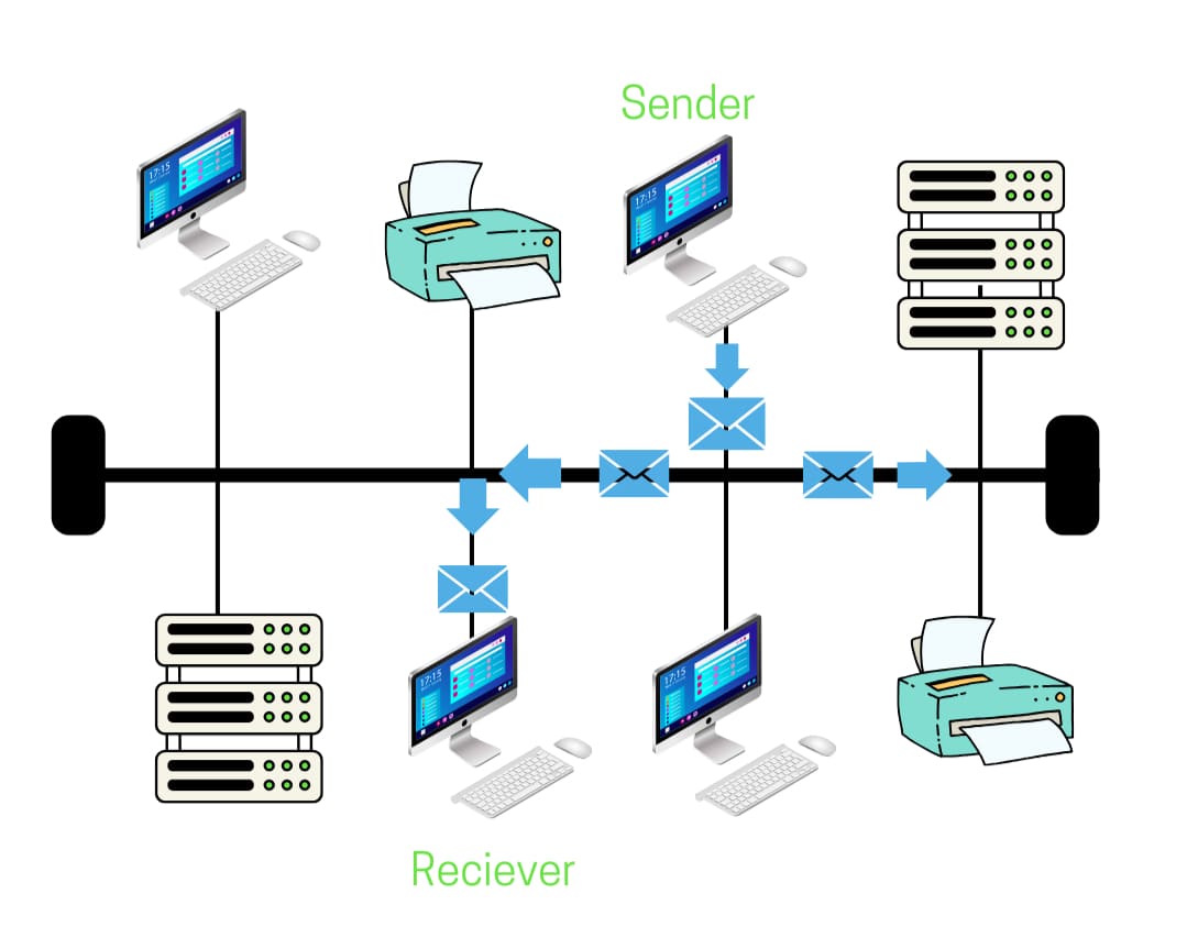
We have broken down the working of the bus topology into 6 simple steps, from the data origin to the data end.
Step 1: Initiation of Data Transmission
The sender, intending to communicate, places data on the bus cable. The data contains information about the source and destination addresses.
Step 2: Signal Propagation
The data then travels in both directions along the central bus cable.
Step 3: Address Matching
Each connected device on the bus cable checks the destination address in the data packet and on match, it accepts the data packet.
Step 4: Data Reception
The receiver then processes the data to retrieve the information.
Step 5: Terminator Action
The terminators at both ends of the bus absorb residual signals, preventing them from reflecting along the cable.
Bonus Step: Collision Detection and Resolution
If multiple devices send data simultaneously, a collision occurs. Protocols like Carrier Sense Multiple Access with Collision Detection (CSMA/CD) detect collisions and manage retransmissions to ensure orderly communication.
How Does Data Travel in a Bus Topology?
The sender of data broadcasts the data on the bus network. Data travels in both directions along the bus cable to reach the desired destination. The terminators at the end of the bus cable ensure that data does not loop in the cable, and ends upon reaching the terminator.
Since the data packet contains information about the destination address, only that particular device can access the information, and the rest of the devices ignore it.
If multiple devices start transmitting data at the same time, there can be collisions of these data packets as they travel on the same bus cable. To avoid these collisions in a bus network, we use the Carrier Sense Multiple Access with Collision Detection (CSMA/CD) protocol.
The CSMA/CD protocol checks the traffic on the bus cable and allows data transmission when the bus cable is free. If a collision still occurs, it halts both the sender for random times and then allows each to resend the data.
Applications of Bus Topology
Some real-life Bus topology applications can be seen in:
● Small offices where a simple, linear connection of devices is sufficient.
● Temporary setups, such as at trade shows or exhibitions, where quick and easy installation is needed.
● Labs and testing environments where devices need to be frequently added or removed.
● Connecting peripheral devices like printers and scanners.
Interested in Implementing Network Topologies with Cisco Devices? Check our Cisco Enterprise Courses or contact learner advisors.

Advantages of Bus Topology
● This topology is simple and cost-effective, making it suitable for small networks.
● Ideal for small networks, where devices can be efficiently connected in a simple, linear fashion without the need for complex configurations.
● One of the easiest topologies to implement, requiring minimal setup and configuration, making it ideal for networks with fewer devices.
● The use of a single backbone cable reduces the overall cost of the network, as it requires less cabling than other topologies like star or mesh.
● Since devices are directly connected to the backbone cable, the initial cost of installation is relatively low compared to more elaborate topologies.
● Adding new devices to a bus topology is simple; you can just attach them to the backbone without significant changes to the overall network.
Disadvantages of Bus Topology
● Difficult to troubleshoot if the entire network goes down, as pinpointing the issue is challenging due to the shared communication medium.
● Not suitable for large networks, as performance and reliability decline with network growth, making it impractical for larger setups.
● Both ends of the main cable require terminators to prevent signal reflection, adding to the complexity.
● Troubleshooting device failures is challenging, making maintenance time-consuming and tough to isolate problems related to specific devices.
● If the main cable (backbone) is damaged, the entire network can go down, dividing it into two parts.
● Adding new devices to the network can slow down the system as the traffic load increases.
Best Practices to Set Up a Bus Topology Network
To implement a bus topology effectively, follow the given set of practices:
1. Ensure that the backbone cable and terminators are of high quality.
2. Keep the number of connected devices within a manageable range to maintain network performance.
3. Design the network with future expansion in mind, allowing for easy addition of new devices.
4. Organize and secure cables to avoid physical damage
Alternatives to Bus Topology
There are several other network topologies that you might consider in place of the bus topology. The two popular choices to use instead of bus topology are star topology and tree topology.
1. Star Topology
Star Topology is a great alternative to Bus Topology. While bus topology connects all devices to a single central cable, making it simple and cost-effective, it can suffer from data collisions and is hard to troubleshoot. Star topology, on the other hand, connects all devices to a central hub, making it more reliable and easier to manage, though it may be more expensive due to additional hardware.
2. Tree Topology
Tree Topology can be a beneficial alternative to Bus Topology. Tree topology combines multiple star topologies into a hierarchical structure, improving scalability and organization. Although it may be more complex and require more cabling, the enhanced structure and manageability make tree topology a strong choice for larger networks.
Conclusion
Bus topology remains a fundamental concept in network design, offering simplicity and cost-effectiveness for small networks. Despite its limitations, such as potential data collisions and difficulty in troubleshooting, it provides a straightforward approach to connecting multiple devices.
Understanding the advantages and disadvantages of bus topology equips network professionals with the knowledge to make informed decisions about network architecture. As technology evolves, exploring alternative topologies may be beneficial, but the principles of bus topology continue to play a crucial role in foundational network education.

Gautam Kumar
Linkedin Profile: https://www.linkedin.com/in/gautam-sharma-068336173/ Gautam Kumar is a senior network engineer having more than 7 years of experience in different companies in India. His work experience in network support and operation and maintaining of any network makes him one of the most valuable IT professional in industry. He has ...
More... | Author`s Bog | Book a MeetingRelated Articles
#Explore latest news and articles
 13 Dec 2025
What's the Difference Between TCP and UDP?
Understand the key differences between TCP and UDP protocols. Compare TCP and UDP protocols to learn the difference between them using examples and ...
 8 Dec 2025
Cisco Hardware Devices
Cisco hardware devices including cisco router models like 2800, 2900, 3800, 3900 etc. series of routers
 4 Jul 2025
Routing Table in Networking - Meaning, Structure and Uses
Learn about routing tables in computer networks and how they manage data paths, optimize network performance, and ensure efficient data transmission.
FAQ
What is Bus Topology in simple words?
Bus topology is a type of network configuration where all devices are connected to a single central cable, known as the backbone. Data travels along this cable in both directions until it reaches its intended recipient.
Is Bus Topology still used today?
While it’s not commonly used in modern large networks, bus topology is still used in small, temporary networks, older systems, or for educational purposes due to its simplicity and cost-effectiveness.
How can I troubleshoot issues in Bus Topology?
Troubleshooting can be tricky because all devices share the same communication medium. It’s often necessary to check each device, cable connection, and terminator. Tools like a cable tester or network analyzer can help identify issues, but pinpointing the exact problem may still be difficult without disrupting the network.
What is tap in bus topology?
In bus topology, a tap is a connector that links individual devices to the main communication line (the bus). It allows devices to send and receive data by tapping into the shared medium, facilitating communication across the network.
How many cables are needed in bus topology?
In a bus topology, only one central cable (the bus) is needed to connect all devices.
How to create bus topology on Cisco Packet Tracer?
To create a bus topology in Cisco Packet Tracer, connect all devices to a single central cable using appropriate network interfaces. Use switches or hubs to simulate the central bus, ensuring all devices are linked to this central point.
Comments (0)
Popular posts


What are the Different Types of Network ...
26 Jun 2026
What is the Syllabus for CCNA ...
26 Jun 2026
Transmission Media and Its Types in ...
6 Jun 2026
CCNA Exam Fees and Expenses Breakdown
25 Aug 2025Recent posts

What are IDS and IPS in Network ...
2 Jul 2026
Top 7 Network Security Protocols You ...
2 Jul 2026
Network Security Generalist ...
2 Jul 2026
Top Network Security Interview Questions ...
2 Jul 2026
What is the Syllabus for CCNA ...
26 Jun 2026Upcoming batches


Contact learning advisor