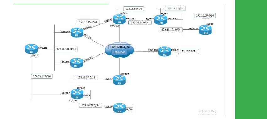
Task
● Configure two GRE tunnels between R4 and R5 as follows:
● Tunnel45 with IPv4 addresses 172.16.0.Y/24, where Y is the router number, sourced from VLAN 45 Ethernet link.
● Tunnel100 with IPv4 addresses 172.16.0.Y/24, where Y is the router number, sourced from VLAN 100 Ethernet link.
● Configure IPv4 static routes on R5 for R4’s Loopback0 interface via both the DMVPN cloud and Tunnel45.
● Configure IPv4 static routes on R4 for R5’s Loopback0 interface via both the DMVPN cloud and Tunnel45.
● The static routes on R4 and R5 via the DMVPN cloud should have a higher administrative distance than those on Tunnel45.
● Configure the backup interface feature on R4 and R5 so that if the Tunnel100 goes down, Tunnel45 is activated.
● Tunnel100 state should be determined through GRE keepalives.
● To verify this configuration, ensure that traffic between Loopback0 prefixes of R4 and R5 is routed out DMVPN cloud:
● If R4’s VLAN 100 interface is disabled, traffic is rerouted out on Tunnel45.s
Explanation
By default, the state of a point-to-point GRE interface is determined by routing availability for the tunnel destination. Therefore, as long as the router has a route for the tunnel destination, the tunnel interface state will be UP.
This, however, does not account for possible transit problems or devices filtering GRE which is IP protocol number 47. To fix the problem, GRE keepalives can be enabled on point-to-point GRE tunnels.
GRE keepalives are implemented in such a way that it can be enabled on one side of the tunnel only, which means only that side can track end-to-end GRE connectivity between the tunnel endpoints and update the GRE interface status accordingly.
GRE keepalives are enabled with the interface-level command keepalive , with interval defining the frequency in seconds for sending keepalives and retries defining the maximum number of keepalives being sent after the first failed keepalive before the tunnel interface state changes to DOWN.
So with configuration keepalive 1 3, the router will send a GRE keepalive every 1 second; upon the first failed keepalive it will send an additional 3 keepalives, and if all failed, the interface goes into DOWN state.
The state of multipoint GRE tunnel interfaces, such as those used in DMVPN scenarios, cannot be monitored through GRE keepalives, because there is no single destination for the tunnel.
The mGRE tunnel interface is always in the UP state. In DMVPN setups, the spoke mGRE tunnel interface can be determined by the spoke being able to successfully register to the hub or not via NHRP if the if-state nhrp interface-level command is configured, but this is not possible for the hub, so the hub interface is always in the UP state.
The design problem in this case is that R4 and R5 cannot actively determine whether the DMVPN path is still functional. Based on the NHRP entries and possibly IPsec state if configured with DMVPN, both hub and spokes will know if there is hub-to-spoke connectivity or not.
However, this does not affect the mGRE interface, which is always in the UP state; and if static routing is configured over DMVPN, this may result in traffic blackholing. If dynamic routing is used over DMVPN cloud and problems appear in the transit path, this will trigger the routing protocol to converge over alternate paths if available.
In this case, the problem is fixed through the use of backup interface functionality. Point-to-point GRE Tunnel100 interface is using the same source and destination IPv4 addresses as the DMVPN network between R4 and R5.
By implementing GRE keepalive, any problems in the transit path that may affect the DMVPN network will be detected by Tunnel100 and cause the interface status to go DOWN. When Tunnel100 interface goes DOWN, this will trigger the backup interface, which is Tunnel45 to go UP, which also activates the static route configured over Tunnel45.
Verify that the backup interface is correctly configured, and Tunnel45 waits for Tunnel100 to go DOWN to become active.
R5
show backup
sho ip interface brief | i Tunnel
R4
show backup
sho ip interface brief | i Tunnel
R5
show ip route 10.1.4.4
ping 10.1.4.4 source loopback0
traceroute 10.1.4.4 source loopback0
R5
debug backup
Backup events debugging is on
configure terminal
Enter configuration commands, one per line. End with CNTL/Z.
interface GigabitEthernet0/0.100
shutdown
R5#
R5
show backup
sho ip interface brief | i Tunnel
Verify that traffic between Loopback0 is now routed over GRE Tunnel45; although both DMVPN and Tunnel45 interfaces are active, static route is preferred via Tunnel45 due to lower administrative distance.
R5
show ip route 10.1.4.4
show ip static route
ping 10.1.4.4 source loopback0
traceroute 10.1.4.4 source loopback0
When R4's VLAN 100 interface is re-enabled, Tunnel100 interface is re-activated as GRE keepalives are functional and all traffic is re-routed over the DMVPN cloud.
R4
configure terminal
Enter configuration commands, one per line. End with CNTL/Z.
interface GigabitEthernet0/0.100
no shutdown
R5
show backup
show ip route 10.1.4.4
traceroute 10.1.4.4 source loopback0
Verify that GRE tunnel keepalives are enabled on Tunnel100.
R5
show interfaces tunnel100
R5
debug tunnel keepalive
Configuration
R4:
interface Tunnel45
ip address 172.16.0.4 255.255.255.0
tunnel mode gre ip
tunnel source 172.16.45.4
tunnel destination 172.16.45.5
!
interface Tunnel100
ip address 172.16.0.4 255.255.255.0
tunnel mode gre ip
tunnel source 169.254.100.4
tunnel destination 169.254.100.5
keepalive 1 3
backup interface Tunnel45
!
ip route 10.1.5.5 255.255.255.255 Tunnel45 10
ip route 10.1.5.5 255.255.255.255 172.16.0.5 20
R5:
interface Tunnel45
ip address 172.16.0.5 255.255.255.0
tunnel mode gre ip
tunnel source 172.16.45.5
tunnel destination 172.16.45.4
!
interface Tunnel100
ip address 172.16.0.5 255.255.255.0
tunnel mode gre ip
tunnel source 169.254.100.5
tunnel destination 169.254.100.4
keepalive 1 3
backup interface Tunnel45
!
ip route 10.1.4.4 255.255.255.255 Tunnel45 10
ip route 10.1.4.4 255.255.255.255 172.16.0.4 20
